Vision-Guided-Ball-Balancing-2DOF
2DOF Ball Balancing Plate using STM32, OpenCV, and PID Control
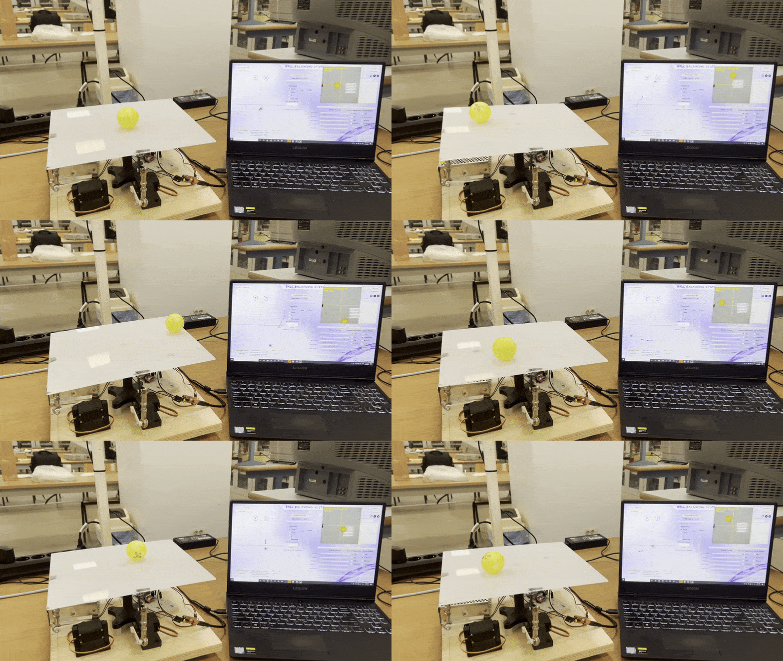
Table of Contents
Project Description
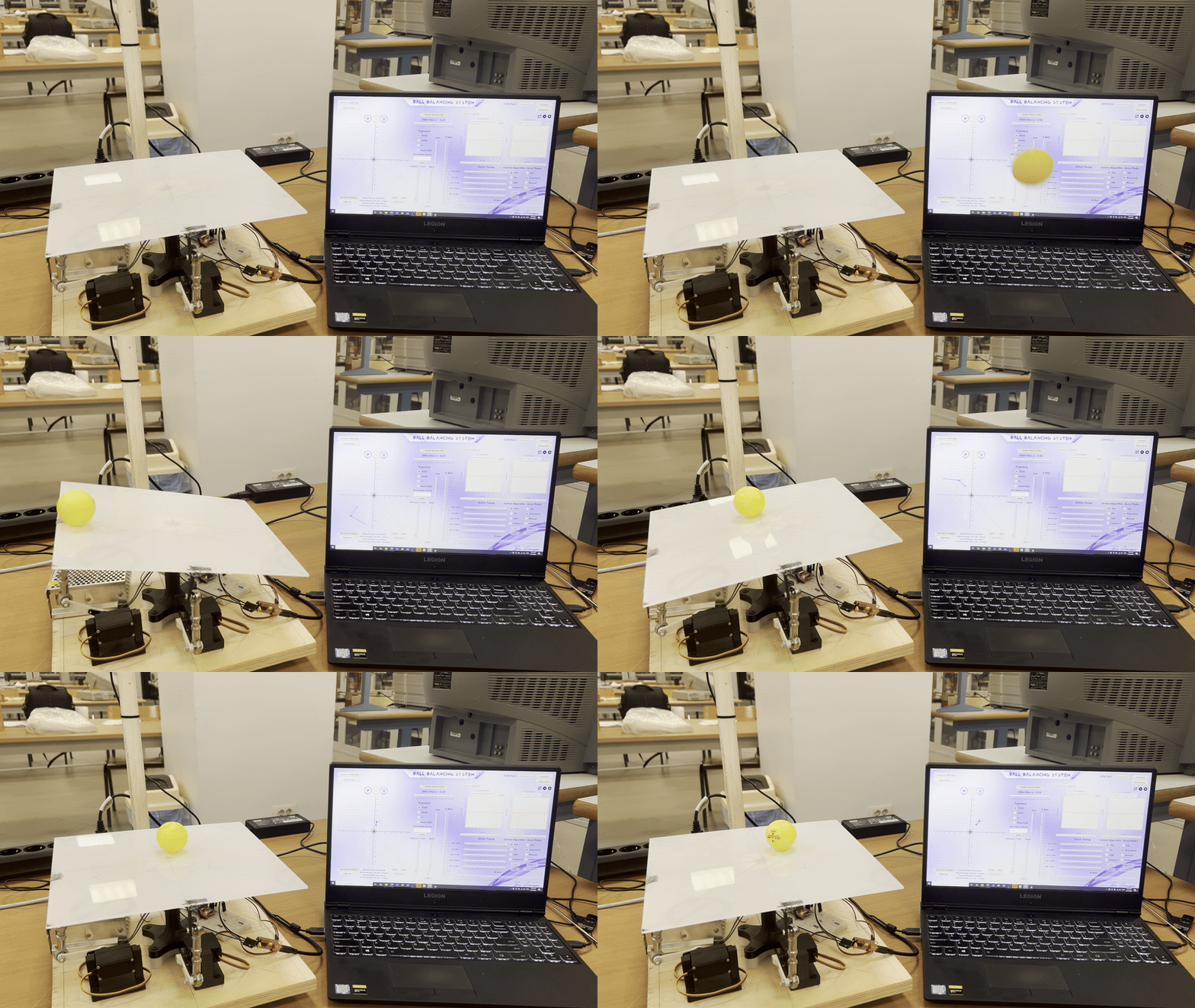
Developed during MCTR601 Mechatronics Engineering course (BSc in Mechatronics Engineering) at the German University in Cairo (GUC), this project implements a real-time ball balancing system using computer vision and embedded control to stabilize and track a ball on a 2-degree-of-freedom (2DOF) tilting platform. The primary goal is to design a system that can dynamically stabilize a rolling ball by adjusting the tilt of a platform in both the x and y directions.
Key Features
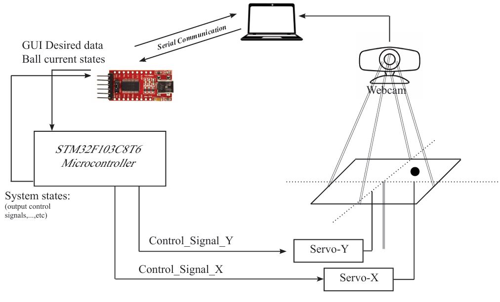
| Feature | Description | |———|————-| | Multi-Control Strategies | PID, PV (Proportional-Velocity Controller), and LQR for dynamic stabilization | | Trajectory Tracking | Follows predefined paths (circle, figure-8) or user-drawn real-time trajectories via GUI | | Laser Tracking | Ball chases a moving laser dot projected on the platform | | Online Tuning | STM32F103C8T6 communicates online with PC via FTDI Serial Module for parameter tuning and monitoring system states |
Functional Diagram
Technical Stack
Vision System
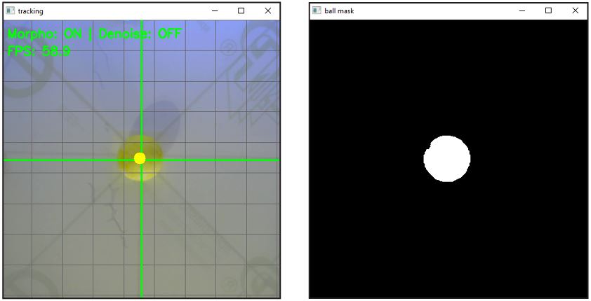
- Python and OpenCV pipeline for image processing, including ball and laser detection.
- HSV color filtering for robust object detection under varying lighting conditions.
- Kalman filter and Exponential Moving Average (EMA) filter for enhancing position stability and trajectory prediction by minimizing noise.
- Velocity estimation by computing positional change over time.
Control System
- PID, PD (PV), and LQR controllers implemented and tuned for stable balancing.
- STM32F103C8T6 Bluepill microcontroller as the control backbone.
- PWM-driven servo motors (MG996R) actuate platform angles based on control input.
- Kalman filter provides reliable velocity estimates used in the control loop.
- Exponential Moving Average (EMA) filter applied to the controller’s output for smoothing.

GUI Interface
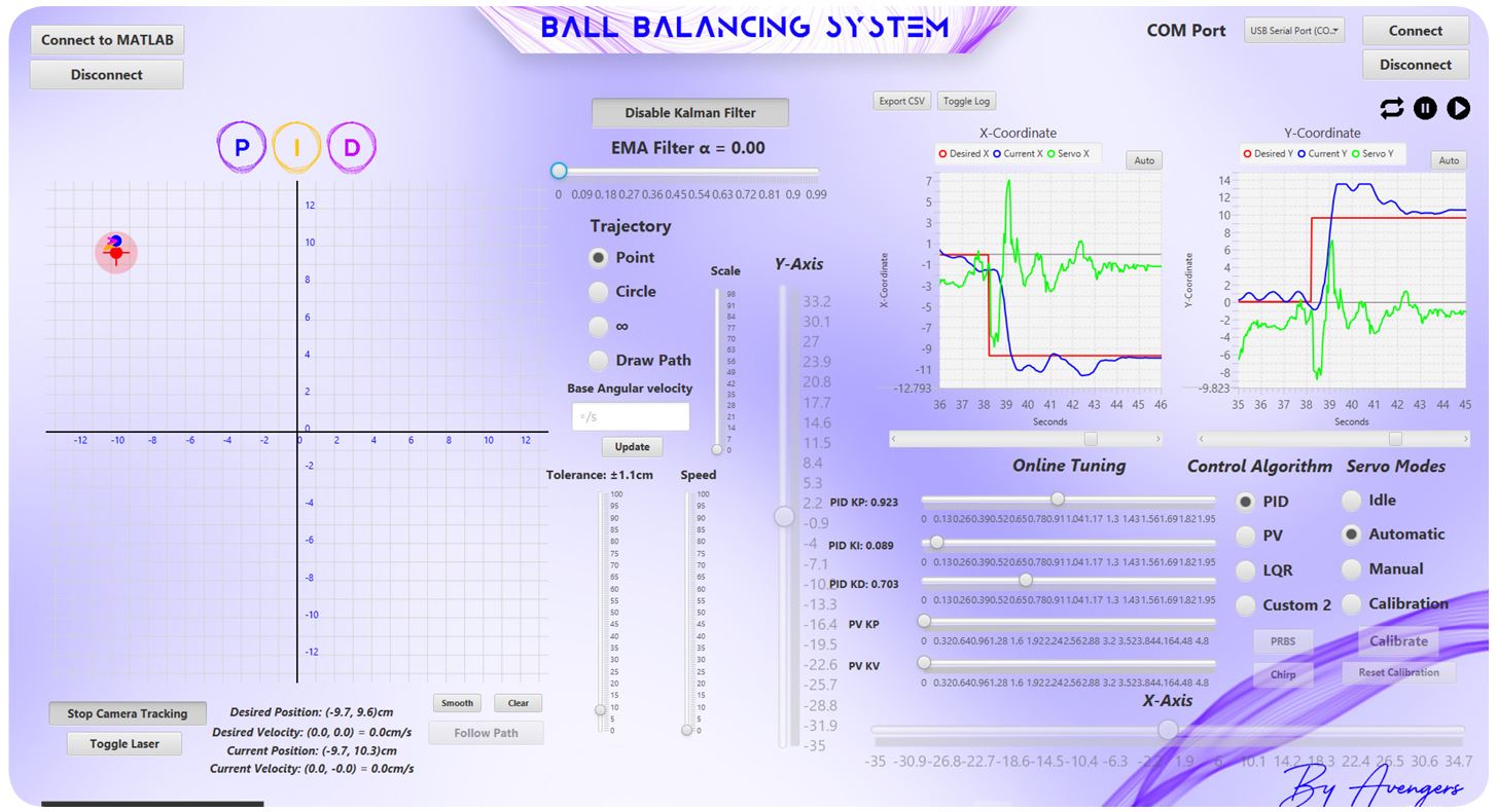
- Java-based Graphical User Interface (GUI) powered by JavaFX provides full user control.
- Enables interactive trajectory drawing, mode selection, control algorithm switching, real-time monitoring, data logging, and online parameter tuning.
- Communicates with the STM32 via UART through FTDI and opens a TCP/IP socket for communication with external software like MATLAB or Python.
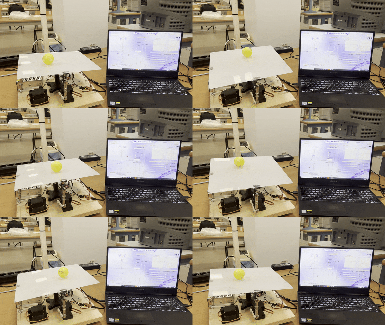
Trajectory tracking
-Circle trajectory
Hardware Components
- 2x MG996R Servo Motors: High-torque servos for precise two-axis tilt control.
- USB Webcam: Mounted above the platform to capture real-time video of the ball’s position.
- Laser pointer: Used for detection and tracking.
- STM32F103C8T6 (Bluepill): Low-cost microcontroller serving as the system’s control backbone.
- USB to TTL Converter - FT232RL FTDI Serial Module: Used for communication between the PC (GUI) and the STM32.
- Power Supply
- Buck Converter XL4015
- Power Distribution Board
-
Tiltable platform
Project Highlights
- Multidisciplinary Integration: Effectively integrates embedded systems, computer vision, and control theory.
- Real-Time Performance: Designed for real-time dynamic ball balancing, with a vision pipeline maintaining tracking performance up to 60 FPS. System components work cohesively to achieve real-time stabilization.
System Architecture
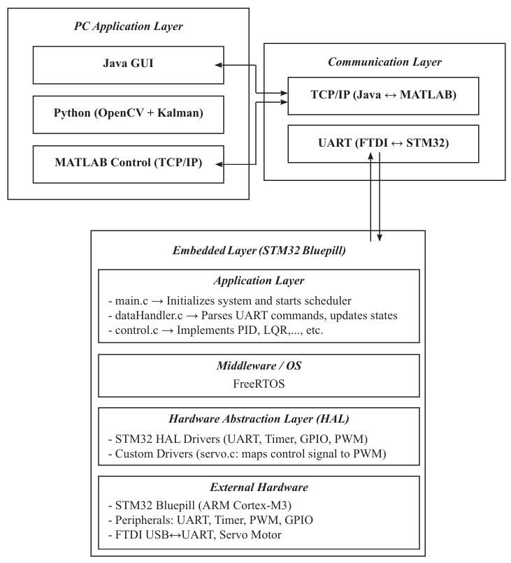
The system follows a layered architecture structure to ensure modularity, scalability, and maintainability.
- PC Application Layer: Hosts the Java GUI, Python program (using OpenCV and Kalman filter for image processing and tracking), and can interface with MATLAB Control via TCP/IP.
- Communication Layer: Handles communication between the PC and the embedded system via UART (using an FTDI converter) and enables PC-to-PC communication (e.g., Java GUI to MATLAB) via TCP/IP.
- Embedded Layer (STM32 Bluepill):
- Application Layer: Contains the main system logic (
main.c,dataHandler.c,control.c,servo.c). - Middleware / OS: Utilizes FreeRTOS scheduler.
- Hardware Abstraction Layer (HAL): Includes STM32 HAL Drivers and custom drivers (
servo.c). - External Hardware: The STM32 Bluepill and its peripherals.
- Application Layer: Contains the main system logic (
This architecture allows for seamless integration between software and hardware for responsive, accurate control.
Hardware
The physical system consists of a flat platform mounted on two servo motors arranged orthogonally, controlling tilt along the X and Y axes.
- Servo Motors (2x MG996R): Provide precise two-axis control for ball stabilization. Driven by STM32-generated 50Hz PWM signals (500-2500μs pulse width). Torque output of 11kg·cm at 6V and angular velocity of 0.15sec/60°. Metal gear transmission for durability. Connected to the platform via 47mm servo arms.
- Webcam: Captures live video frames at runtime.
- STM32F103C8T6 (Bluepill): Serves as the control backbone. Receives processed ball position data via Bluetooth from the PC (Note: Later sections mention UART/FTDI and TCP/IP for PC communication), applies the selected control algorithm, and generates PWM signals for servos.
- FTDI USB to TTL Converter: Facilitates serial communication between the PC and STM32.
- Power Supply and Buck Converter (XL4015): Provide necessary power to the components.
Technologies
The project integrates several key technologies:
- Microcontroller: STM32F103C8T6 (Bluepill) running FreeRTOS.
- Computer Vision: Python and OpenCV for real-time image acquisition, preprocessing, object detection (ball and laser) and position/velocity estimation.
- Control Theory: Implementation of PID, PD (PV), and LQR control algorithms. System modeling, linearization, and transfer function analysis. Discretization techniques for digital implementation.
- Actuation: Servo Motors (MG996R) driven by PWM signals from the STM32.
- User Interface: Java-based GUI (JavaFX) for comprehensive system control and monitoring.
- Communication: UART (via FTDI) and TCP/IP for data exchange and external control integration (MATLAB/Python).
How to Use It
The system is controlled primarily through a Java-based Graphical User Interface (GUI).
- Hardware Setup: Ensure the ball balancing platform, servos, webcam, STM32 (Bluepill), FTDI converter, and power supply are correctly connected.
- Start Vision System: Run the Python program which uses OpenCV to capture video from the webcam and perform ball/laser tracking. An interface allows selecting the correct camera.
- Start GUI: Launch the Java GUI application.
- Connect Hardware: Use the GUI to establish communication with the STM32 via the FTDI serial module.
- Calibration (if needed): The GUI may offer a calibration mode. The Python vision system includes real-time trackbars for tuning HSV thresholds for ball and laser detection.
- Mode Selection: Choose between operating modes like idle, automatic, manual, or calibration via the GUI.
- Control Algorithm Selection: Dynamically select the desired control algorithm (PID, PD, LQR, or custom) through the GUI.
- Parameter Tuning: Adjust control parameters (Kp, Ki, Kd, EMA alpha, etc.) online via the GUI for fine-tuning the system response.
- Setpoints & Trajectories: Set desired ball positions or select/draw predefined trajectories (circle, figure-eight, custom paths) via the GUI. Input desired angular velocity for trajectory execution.
- Monitoring: View real-time tracking of the ball’s position on a coordinate grid and visualize system input-output behavior through plotted graphs on the GUI.
- Data Logging: Export recorded data as CSV files for offline analysis.
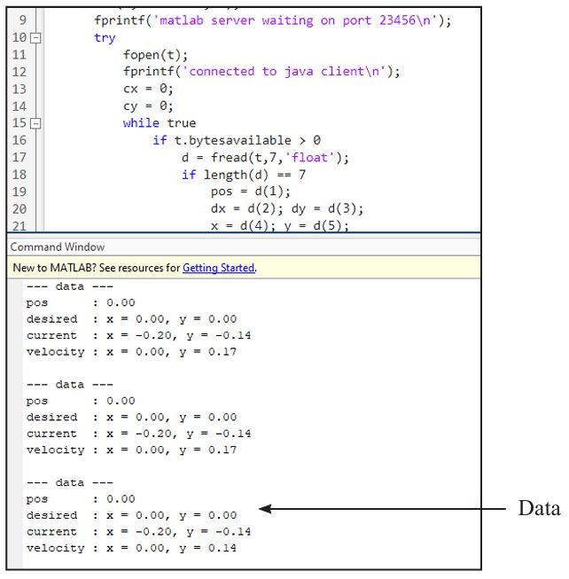
- External Control (Optional): The GUI can connect to MATLAB or Python scripts via TCP/IP, allowing control signals to be generated externally, facilitating experimentation with advanced control techniques.
Contributors
- Ali Emad
- Marawan ElSayed